

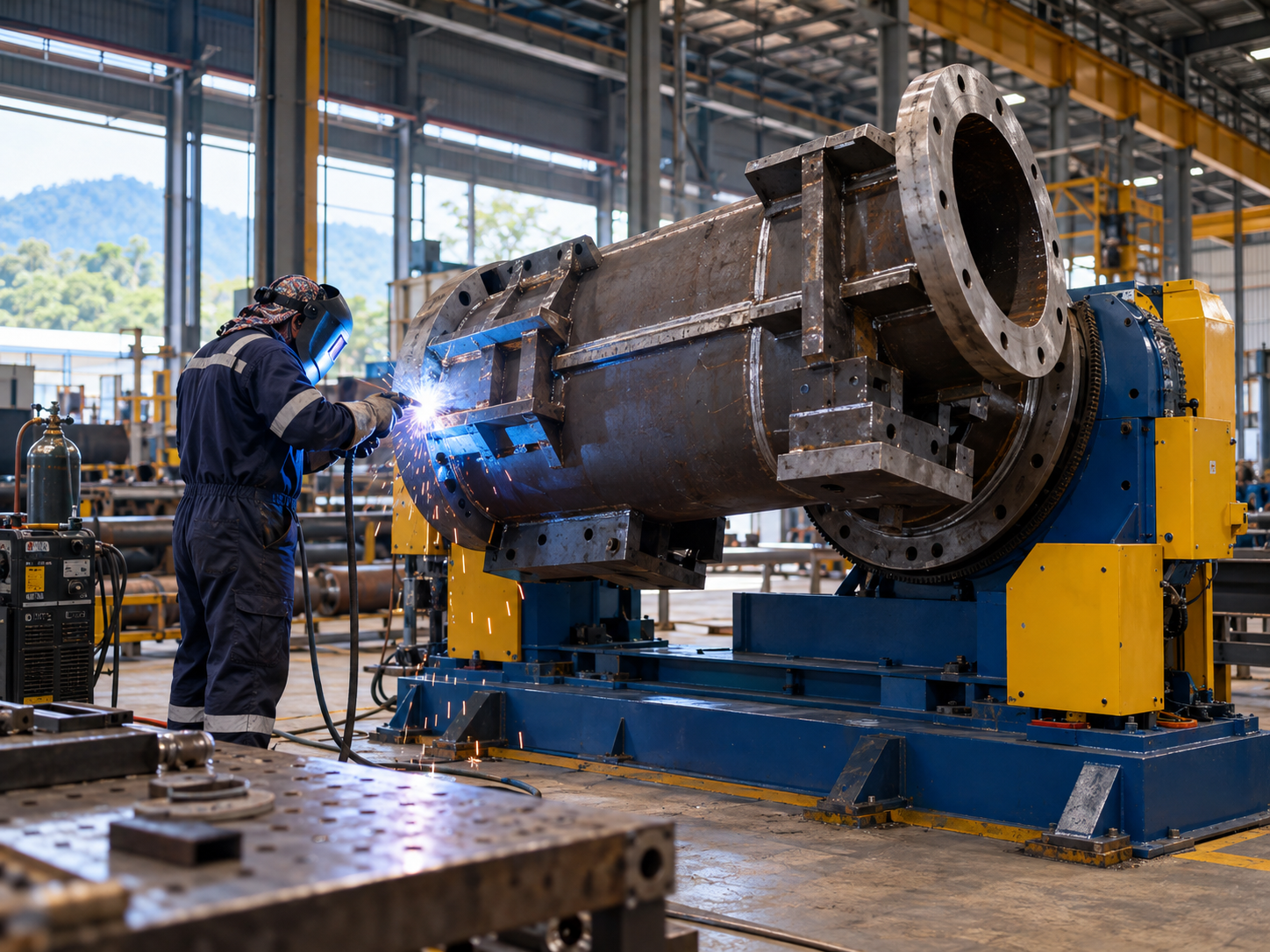
Choosing a welding positioner in Malaysia is not simply a matter of matching the machine’s advertised kilogram capacity to the weight of a steel component. An appropriate unit must carry the combined weight of the workpiece and fixture, tolerate the position of their centre of gravity, rotate at the required welding speed and provide enough clearance to move the assembly safely.
For a metal fabrication workshop, these details determine whether a positioner helps the welder maintain a practical working angle or creates an unstable, awkward setup. The same questions matter when a manufacturer is planning repetitive circumferential welds or adding a workpiece positioner to an automated cell.
This guide explains the main positioner types, shows how to assess load and rotation requirements, and gives Malaysian engineering and purchasing teams a checklist to prepare before requesting an equipment quotation.
Which Type of Welding Positioner Fits the Workpiece?
First identify how the workpiece must move. A tilting table, a set of turning rolls and a headstock-and-tailstock arrangement are not interchangeable, even when their load capacities appear similar. The shape of the fabrication and the weld path usually narrow the choice.
| Positioning equipment | Typical workpiece | Movement | What to confirm |
|---|---|---|---|
| Rotary turntable | Small circular assemblies, flanges and rings | Rotation around one axis | Table orientation, axial load, eccentricity and speed stability |
| Tilt-and-rotate positioner | Brackets, pipe spools and varied fabrication jobs | Powered rotation with adjustable table angle | Rated tilt and rotation moments, centre-of-gravity limits and swing clearance |
| Turning rolls / welding rotators | Cylindrical vessels, tanks and long pipes | Workpiece rolls on driven and supporting rollers | Diameter range, combined roller-set loading, traction and speed matching |
| Headstock-and-tailstock positioner | Long frames or heavy structures needing support at both ends | Supported rotation about a defined axis | Support alignment, fixture design, span and synchronisation |
| Robotic L-type or multi-axis positioner | Repeatable assemblies within a welding cell | Programmable coordinated rotation and positioning | Robot integration, torque, payload, repeatability and cell guarding |
For general fabrication, ASB Welding lists the ProArc PT welding positioner series, with published capacities ranging from 100 kg to 20,000 kg. For smaller jobs, its PT-102/202 digital welding positioners are described as 100 kg and 200 kg models with selectable rotation-speed ranges. Those figures are starting points for evaluating a model, not proof that every workpiece of that mass can be safely mounted in every orientation.
For pipe and vessel fabrication, compare the workpiece configuration with self-aligning turning rolls rather than treating a conventional tilt-and-rotate table as the default. ASB’s published self-aligning range covers different cylindrical diameters and turning capacities; the correct model still depends on the complete support arrangement.
How Should Load Capacity and Centre of Gravity Be Evaluated?
Calculate the total supported load first, then assess where that load acts. The workpiece, chuck, faceplate adapters, fixtures and any other attached tooling contribute to the load. An uneven load can generate a substantial moment even when the total mass is below a positioner’s headline rating.
Include the weight of the fixture
If a component weighs 180 kg and the holding fixture weighs 35 kg, the positioner carries at least 215 kg before any additional attached equipment is considered. Comparing only the 180 kg component with a machine’s rated capacity would understate the installed load.
Check the distance to the combined centre of gravity
The centre of gravity (CG) is the point through which the combined load’s weight effectively acts. An offset from the rotation axis produces a different demand from a balanced load. The distance from the table surface to the CG also affects the tilting arrangement.
For an initial illustration, suppose the assembled workpiece and jig have a combined mass of 215 kg and an eccentricity of 0.12 m from the relevant axis. The corresponding gravitational moment at the worst orientation is approximately:
215 kg × 9.81 m/s² × 0.12 m = 253 N·m
This is an illustrative static calculation, not a machine selection or a complete drive-sizing calculation. The tilt-axis geometry, inherent overhang, orientation, dynamic effects and the manufacturer’s separate rotation and tilt ratings also matter. Do not use the simplified figure as permission to operate a machine.
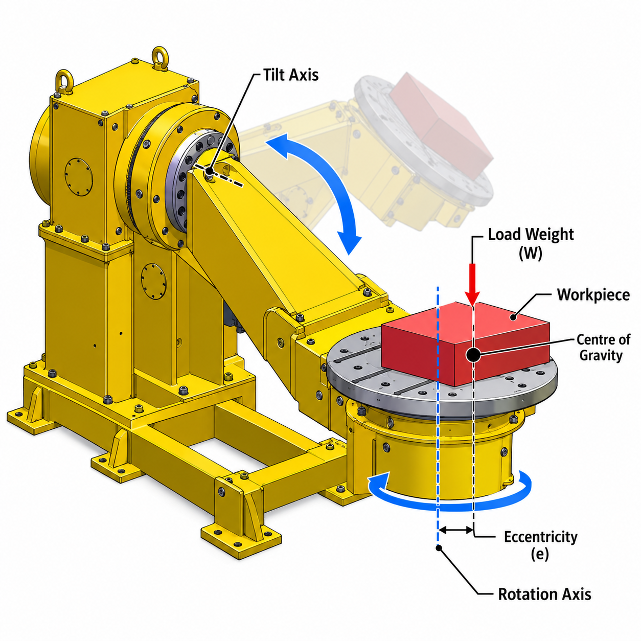
Koike’s technical explanation of welding positioner sizing gives a useful reference for understanding centre-of-gravity location, tilt and rotation moments, and swing clearance. Its calculations illustrate why capacity must be assessed at the actual loading geometry rather than by weight alone.
How Do You Choose the Right Rotation Speed?
The required rotation speed depends on the weld path, not simply whether the workshop uses MIG or TIG welding. For a circumferential weld, the positioner must move the joint past the torch at a travel speed suitable for the approved welding procedure.
For a circular weld at a constant radius, a first-pass relationship is:
Positioner speed (rpm) = welding travel speed (mm/min) ÷ (π × weld diameter in mm)
As an example, a 600 mm diameter circular joint welded at an illustrative travel speed of 300 mm/min would require approximately 0.16 rpm (300 ÷ 1,885). This is a geometry calculation only; the appropriate welding travel speed must come from the actual process and welding procedure.
ASB’s PT-102/202 product page lists several selectable speed ranges, including a 0.15–4 rpm option. A buyer should check whether the selected range covers both the slowest and fastest required weld paths, with stable movement under the actual eccentric load. Review the PT-102/202 specifications before deciding on the required model and drive configuration.
Parts that are not circular, vary in radius or change orientation during welding may need different motion control or a programmed automation solution. A single rpm value should not be assumed suitable for every section of such a joint.
What Dimensions and Installation Conditions Must Be Checked?
Before choosing a unit, measure the full rotating assembly—not only the nominal diameter of the metal part. Chucks, clamps, projecting brackets and fittings may extend beyond the workpiece envelope.
| Measurement or condition | Why it matters | Information for the supplier |
|---|---|---|
| Maximum assembled weight | Defines supported mass, including fixtures | Workpiece and tooling weights separately |
| CG height and eccentricity | Influences allowable rotation and tilt loading | Estimated CG location for each mounting orientation |
| Largest outside dimensions | Determines collision-free movement | Length, width, height, maximum swing radius and projections |
| Weld diameter and travel-speed range | Determines required rotation control | Minimum and maximum required rpm, with process details |
| Mounting and clamping arrangement | Controls how the load is secured | Chuck, T-slot, faceplate, adaptor and fixture requirements |
| Workshop environment | Affects safe installation and use | Available footprint, lifting access, supply power and extraction |
Check the clearance through the full intended tilt and rotation range. A long workpiece may clear the floor with the table upright but collide with nearby equipment after tilting. The loading and unloading method matters too: assess forklift or crane access, fixture handling and operator reach.
Do not overlook the welding-current return path. Confirm that the positioner is designed for the proposed welding current and that the current returns through the intended arrangement rather than through components such as bearings. ASB describes a dedicated grounding arrangement on the ProArc PT range; confirm the particular model and installation details in writing.
When Are Turning Rolls or Robotic Positioners More Suitable?
A conventional welding positioner is useful when a workpiece can be clamped securely to a rotating or tilting table. For a long cylindrical vessel, supporting the load on turning rolls may be a more practical arrangement.
ASB lists ProArc turning rolls for pipes and vessels, alongside self-aligning models that accommodate specified diameter ranges. Both support rotational welding, but the actual roller-set capacity and workpiece geometry must be reviewed. ASB’s general ProArc turning-roll page presents differing capacity figures, so obtain the model-specific datasheet before citing a maximum rating.
For automated fabrication cells, a positioner may need to move in coordination with a robot. ASB’s robotic L-type positioner and robotic headstock-and-tailstock systems are relevant starting points when discussing programmable external axes, long fabrications and repeatability.
For circumferential welding, ASB also lists an E.Z.Arc system built around positioners, turning rolls and associated components. This is a distinct purchasing question from selecting a basic manual-workshop positioner: integration, controls, fixtures and welding procedure requirements all need to be assessed together.
Readers exploring robotic integration can consult ASB’s existing guide to robotic welding systems in Malaysia for a broader introduction without repeating that article’s automation overview here.
What Safety Checks Belong in a Positioner Purchase?
A welding positioner moves heavy components near people and welding equipment. The purchasing review must consider the actual installation and operating cycle, including the risks from rotating or tilting masses, pinch points, unexpected movement and falling or improperly secured workpieces.
- Load restraint: Check the specified clamping system and the manufacturer’s allowable loading configurations.
- Access and guarding: Establish exclusion zones and protection around moving components; assess any pinch and trapping points.
- Controls: Confirm suitable start/stop, emergency-stop and isolation arrangements, including how unexpected restart is prevented.
- Welding conditions: Consider fume extraction, arc screening, welding-current return and cable routing during rotation.
- Commissioning: Require documented setup, inspection and operator training appropriate to the machine and site.
For Malaysian safety context, the Department of Occupational Safety and Health’s Machinery Safety Basic e-Guide explains machinery risk assessment and machine guarding. The UK’s Health and Safety Executive guidance on welding fume controls is a supplementary international technical resource. UK guidance should not be presented as Malaysian legislation.
For final purchase and commissioning decisions, use the machine manufacturer’s instructions, the site’s risk assessment and the Malaysian requirements applicable to the workplace.
What Should a Malaysian Buyer Ask Before Requesting a Quotation?
Technical buyers can reduce unsuitable quotations by sharing the operating requirements in a structured form. A supplier cannot validate capacity or motion simply from the words “heavy-duty welding positioner.”
| RFQ item | Information to provide or request | Decision supported |
|---|---|---|
| Workpiece and fixture | Sketch or drawing; part mass, fixture mass, dimensions, CG estimate | Payload and moment verification |
| Weld and motion | Weld location, welding process, required joint travel speed, tilt range | Rotation drive and control selection |
| Handling and installation | Workshop footprint, loading method, access clearance, electrical supply | Physical fit and installation feasibility |
| Machine documentation | Rated load diagram, maximum moments, model datasheet, control details | Technical compliance with intended use |
| Support and ownership | Delivery scope, commissioning, training, service response and spares | Lifecycle support and downtime risk |
| Commercial proposal | Included fixtures, optional controls, warranty, lead time and total quoted scope | Like-for-like supplier comparison |
Compare the complete usable system, not only the positioner’s purchase price. A low equipment price can be misleading if the proposed solution omits essential fixtures, controls, installation or site training. Where a workshop handles many changing workpiece sizes, ask how the supplier would validate the proposed range rather than specifying only the most common job.
ASB Welding supplies positioning and welding automation equipment in Malaysia. Buyers can contact ASB Welding with drawings and basic process information to discuss the appropriate positioner or turning-roll configuration and request model-specific technical documentation.
Frequently Asked Questions
Can a welding positioner be used for assembly or inspection as well as welding?
Possibly, provided the manufacturer approves those uses and the fixture, movement and guarding are suitable. The load limits and safe operating procedure still apply even when no welding arc is present.
Does purchasing a positioner remove the need for a qualified welding procedure?
No. A positioner controls workpiece orientation and movement; it does not replace the welding procedure, operator competence, inspection requirements or applicable fabrication code.
What should a buyer check when considering a used welding positioner?
Request the model identification, capacity plate, operating manual, service history and evidence that the controls, emergency stop, drive, bearings and welding-current return arrangement are in acceptable condition. Arrange a competent inspection and trial with a representative load before use.
Should operators receive training before using a new positioner?
Yes. Training should cover safe loading and clamping, load limits, rotation and tilt controls, exclusion zones, emergency stops, isolation and the site-specific risk assessment. Follow the equipment manufacturer’s instructions.
Conclusion: Select for the Real Load and Welding Process
The most useful welding positioner is not necessarily the unit with the largest advertised load capacity. It is the one that safely supports the complete workpiece and fixture, accommodates the actual centre of gravity and swing envelope, and provides appropriate movement for the welding task.
For Malaysian fabrication businesses, the fastest way to narrow the choice is to document the maximum assembly weight, CG location, required rotation speed and mounting arrangement before comparing model specifications. Ask the supplier to validate the proposed operating configuration and explain how it will be commissioned and supported.
Need Help Selecting a Welding Positioner in Malaysia?
ASB Welding supplies ProArc positioners, turning rolls and welding automation solutions for different fabrication requirements. Share your workpiece drawing, weight, fixture details and intended welding process so the technical team can discuss a suitable equipment configuration.
Discuss Your Welding Positioner Requirements with ASB Welding